
Every commercial building has a unique electrical system dependent on its layout, power demands, and the AHJ. You may be inspecting a single building or a multi-building property. Don’t get overwhelmed. Break down your inspection of the system by tracing it from the visible utility equipment to the service entrance equipment, and then to any downstream equipment.
Read labels. Follow the ComSOP. And always repeat your safety procedures throughout. This video demonstrates these key aspects of a commercial electrical inspection:
To begin to understand the electrical system of a building, start at the service entrance equipment, using Section 6 of the ComSOP under Electrical as your guide:
1. Locate where the power enters the building from the utility to the service entrance equipment. Document the location of the:
- building’s meter socket enclosure; and
- service entrance equipment, including the means for disconnecting the service main.
All of this helps you begin to understand how power is distributed throughout the building. Where visible, you may also see the service lateral/drop, service entrance conductors, and any visible grounding and bonding.
2. Inspect the equipment location for clearance, access, and safety. Create and follow a consistent inspection procedure for electrical equipment and its safety before your approach, such as:
- assessing working space clearances in front, between, and above electrical equipment; and
- Verifying that the equipment is not energized using a non-contact or limited-contact voltage detector.
If any hazards or access issues are present, document them. Note issues like locked panels with no key present. Physically contact the equipment only if it is clearly safe to do so.
3. Inspect the service entrance equipment. You don’t need to remove the dead front or panel cover. This inspection can be completed by opening the panel door, and then:
- confirming that the panel door opens at least 90 degrees;
- visually assessing the physical condition of equipment (i.e., damage, burns, rust, loose connections, etc.);
- documenting the service disconnect and equipment label details;
- determining the service amperage rating;
- checking for missing or illegible labels, unfilled breaker openings, and whether the panel is appropriate for its location (i.e., Type 3 for exterior use); and
- evaluating the overcurrent protection and disconnect by:
- identifying the panel’s maximum rating;
- checking the disconnect’s rating; and
- confirming that the disconnect does not exceed what the panel can handle.
You may also come across larger components, such as switchgear and switchboards. Document their presence, read the labels, locate the disconnects and ratings, and visually assess their condition. Don’t unfasten any screws or operate the equipment.
Understanding Service Amperage Labels and Recognizing Potential Panel Overload
At the service entrance equipment shown in the video, you’ll find a 250 A maximum service amperage rating and a 600Y/347V system configuration (three-phase, common in commercial buildings).
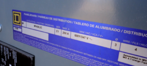
Panel label
The disconnect is rated for 200 A, which is lower than the panel’s 250 A rating. That’s acceptable and safe, as the disconnect should never exceed the panel’s ampacity. A disconnect rated higher than 250 A could overload the panel in the event of a fault.
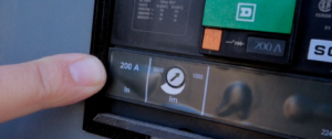
Disconnect label
Inspecting the Subpanel
At this point, you’ve covered where the power enters the building from the utility to the service entrance equipment, and have an understanding of the building’s electrical service size, including the available amperage and system voltage.
Now, you’ll assess any equipment downstream of the service equipment, like subpanels and transformers.
For any electrical equipment, repeat your inspection process:
- assess the equipment location for clearance, access, and safety before coming into contact with it (as outlined in #2 above); and
- perform a visual inspection of the equipment (see #3 above).
At the subpanel shown in the video, you’ll see a 200 A disconnect protecting a 225 A panel. This meets the ComSOP’s inspection requirement to “determine the overcurrent protection and disconnect.”
As a commercial property inspector, the drop from 600V at the main to 240V inside should stand out to you. It’s a clear indication that a transformer is in use on the building-side.
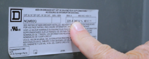
Panel label
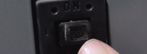
Main Breaker
Inspecting the Transformer
Home inspectors may already be familiar with the concept of a transformer, as single-family homes have a utility-side transformer (pole- or pad-mounted) that steps down high-voltage power to 120/240V for direct distribution through the main panel and property at that voltage.
In commercial buildings, building-side transformers are common. These may step down or step up power to serve specific equipment or distribution systems. For commercial property inspectors, reading equipment labels and inspecting transformers in commercial buildings helps you further understand and document how power is managed throughout the building.
Working space for transformers is a grey area in electrical codes. Some AHJs may waive working space requirements for transformers, but as a general rule, document any access limitations in the event your client needs it examined or serviced in the future.
A good way to locate the transformer, or the equipment it serves, is to trace the conduit that leaves the panel and returns to it. The transformer may be mounted on a platform, as shown in the video, or set at ground level. From there, you can also see what it feeds by following the conduit or reading any other nearby labels.
Inspecting Multiple Buildings on a Property
Inspecting the utility-side electrical equipment is beyond the scope of the inspection, but taking a look during the preliminary walk-through can help you prepare and give you key clues about what to expect.
In the video, the service splits into two runs, each with its own disconnect on the rack. These serve different portions of the property.
At this property, the two runs are:
- a current transformer (CT) panel, a main disconnect, and a distribution panel that feeds one side of the property from the rack. This setup is tied to a single meter that measures usage for the entire property. The CT panel is locked and maintained by the utility and is the means for a utility-controlled split in two directions; and
- another line runs to a transformer and a separate disconnect on the rack. This line supplies the first building shown in the video. That specific building has its own meter and disconnect to measure and control power for that individual structure.
During your inspection of multiple buildings in a campus-like layout, you may find additional main disconnects, meters, and panels spread across the property. Use the visible components and labels to build your understanding.
Take it step by step (or building by building). Start at the utility-side or main service equipment and work your way downstream. Follow the ComSOP and a consistent electrical safety inspection procedure.
Additional Resources for Commercial Property Inspectors: